A rusty metal pipe with a guided wave transducer attached, surrounded by cables and connectors, set in an outdoor grassy area.

Guided Wave Testing: A Long-Range Approach to NDT

Discover the advantages of guided wave testing (GW), understand the basic principles behind the GW method, and explore the variety of techniques for applying guided wave testing in nondestructive testing across industries.

What Is Guided Wave Testing and How Is It Used in NDT?

Guided wave testing is an NDT method that uses low-frequency sound waves to inspect long sections of pipe from a single access point. Instead of moving a sensor along the full length of a pipe, GW sends wave energy down the pipe and listens for reflections that come back from changes in wall thickness, corrosion, or other discontinuities.

This makes GW especially useful for inspecting pipes that are buried, insulated, elevated, or otherwise difficult to reach. A single test location can screen dozens of meters of pipe in both directions without removing insulation, excavating, or gaining access to the full pipe length.

GW is primarily a screening tool. When it identifies an area of concern, a follow-up inspection with another method — such as ultrasonic testing — is typically used to characterize the defect more precisely.

A skilled NDT specialist uses their knowledge of wave behavior, pipe geometry, and signal analysis to set up the test, interpret the data, and identify locations that require closer examination.

The primary objectives of GW in industrial applications include:

  • Screening for Corrosion and Defects: GW detects areas where the pipe wall has thinned due to corrosion, erosion, or mechanical damage.

  • Covering Long Distances: A single test location can screen dozens of meters of pipe in both directions, reducing the number of access points needed.

  • Reducing Downtime and Cost: Because GW can inspect through insulation and coatings without removing them, it reduces the time and cost of inspection compared to conventional point-by-point methods.

Advantages and Limitations of Guided Wave Testing in NDT

GW is used across industries including oil and gas, power generation, chemical processing, and infrastructure. Before considering GW for a pipeline inspection, it helps to understand the main advantages and limitations of the method.

Advantages of Guided Wave Testing

  • Long-Range Coverage: GW can inspect tens of meters of pipe in both directions from a single sensor location, making it far more efficient than conventional point-by-point inspection.

  • Inspects Through Barriers: GW can test through insulation, coatings, and even road crossings without removal, reducing preparation time and cost.

  • Access to Difficult Areas: Buried, elevated, or otherwise inaccessible pipes can be screened from a single accessible location.

  • Efficient Screening: GW quickly identifies areas of concern so that follow-up inspections can be focused where they are most needed.

  • Minimal Surface Preparation: GW typically requires less surface preparation than conventional ultrasonic testing.

  • Improved Safety: By reducing the need to access hazardous or confined areas, GW helps keep inspectors out of high-risk locations.

Limitations of Guided Wave Testing

  • Screening, Not Sizing: GW identifies areas of concern but typically cannot measure the exact size or depth of a defect. Follow-up inspection is needed for precise characterization.

  • Signal Complexity: Welds, bends, supports, and branches in the pipe create reflections that can complicate interpretation. Distinguishing defect signals from structural features requires experience.

  • Sensitivity Limits: GW may not detect very small or gradual defects, especially at greater distances from the sensor ring.

  • Affected by Pipe Condition: Heavy coatings, bitumen wrap, or certain pipe conditions can absorb wave energy, reducing the effective range and sensitivity of the inspection.

  • Requires Specialized Equipment: GW uses purpose-built sensor rings, software, and instrumentation that differ from conventional ultrasonic testing equipment.

  • Defect Orientation: Some types of defects may not reflect the guided wave strongly enough to be detected, depending on their orientation relative to the wave propagation direction.

How Guided Wave Testing Works: Basic Principles

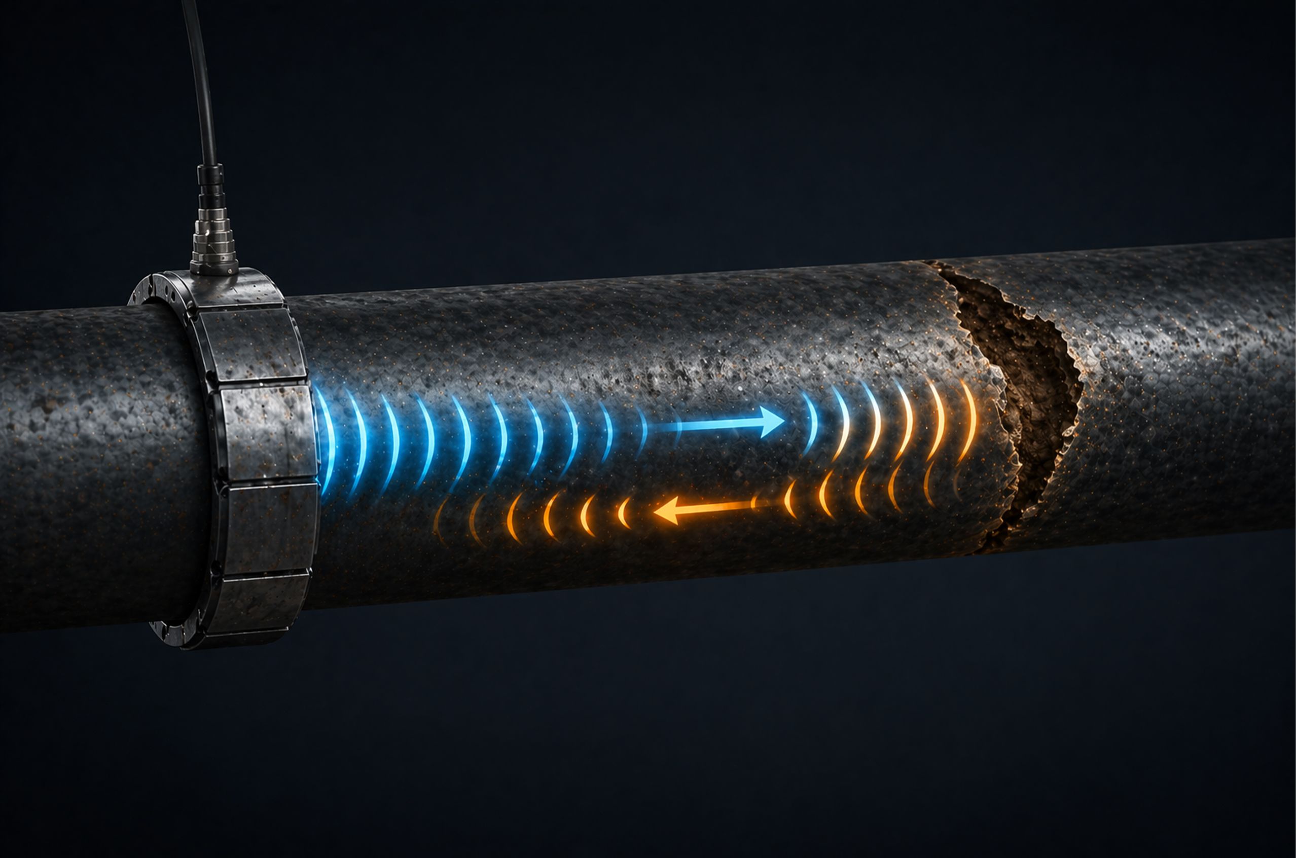
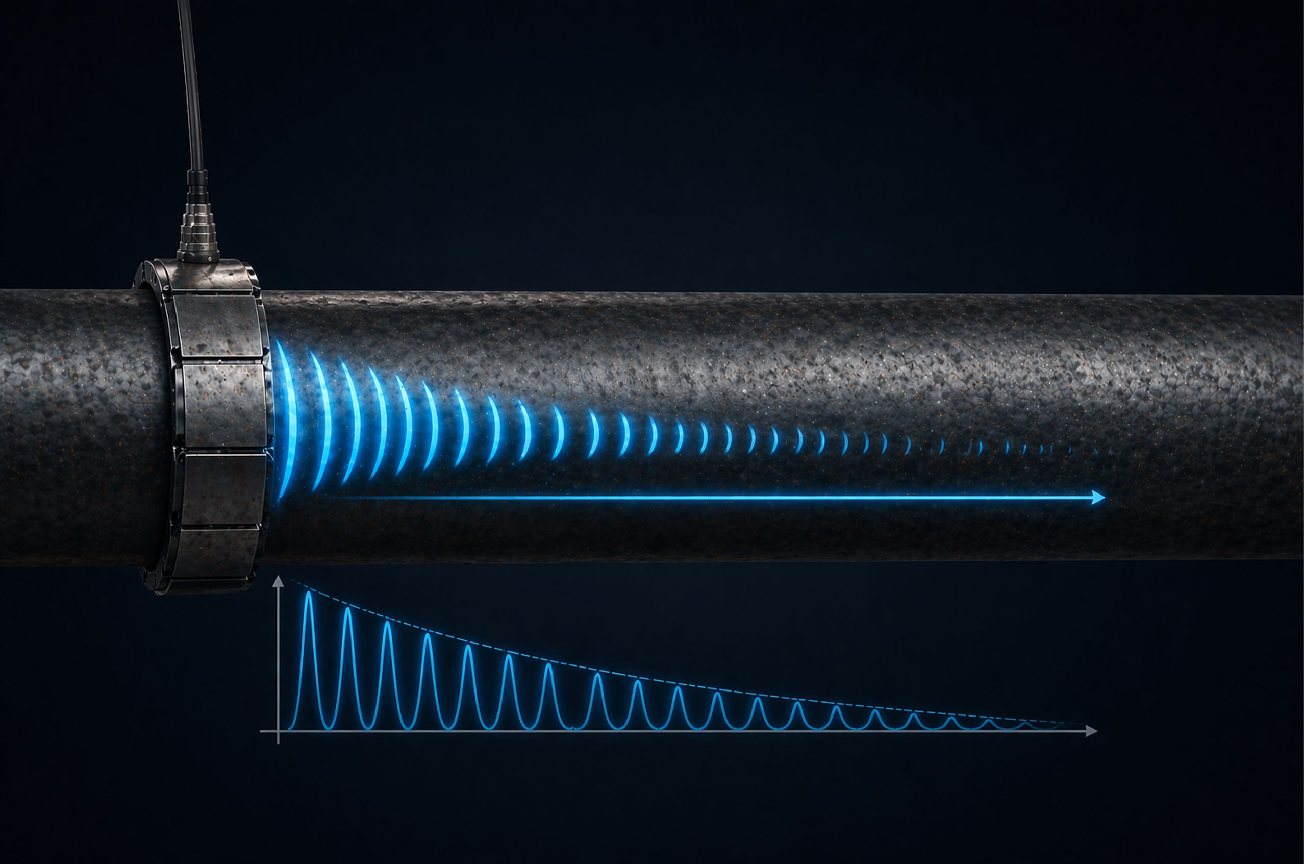
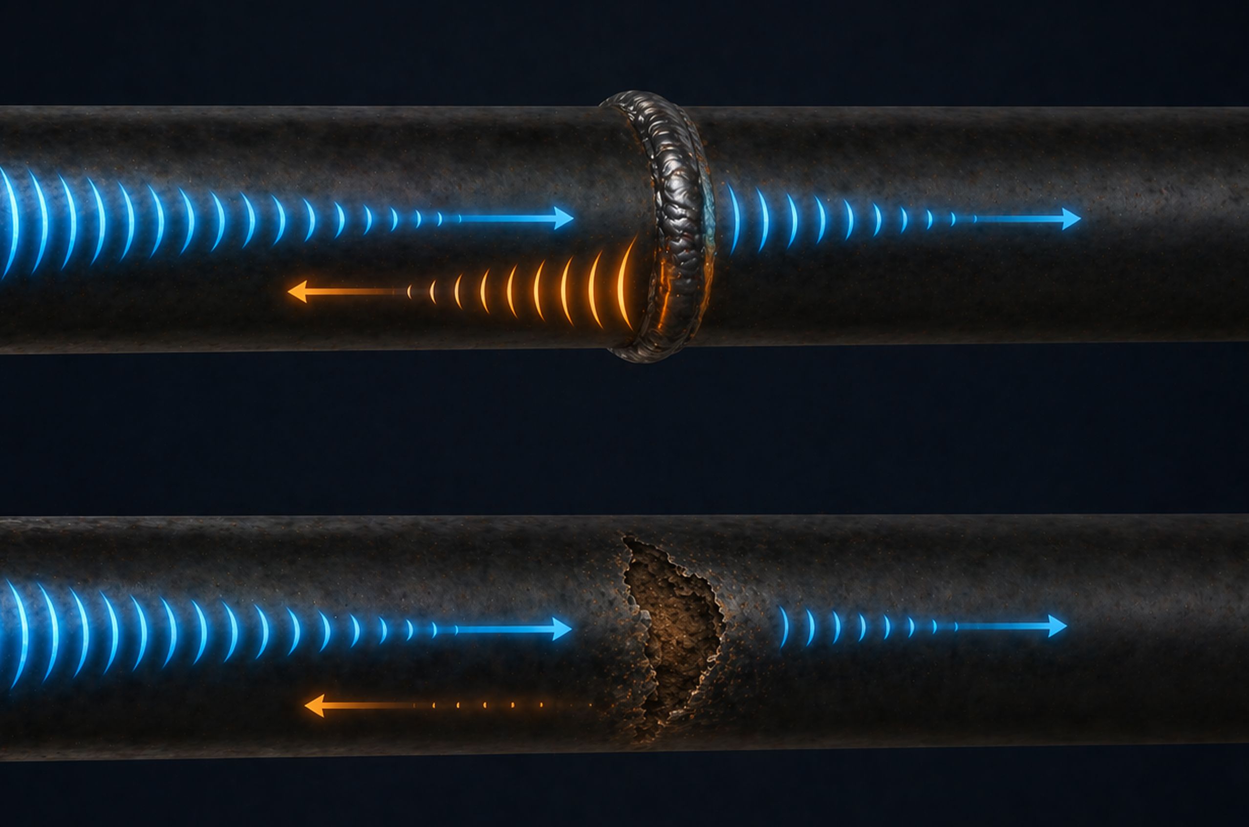
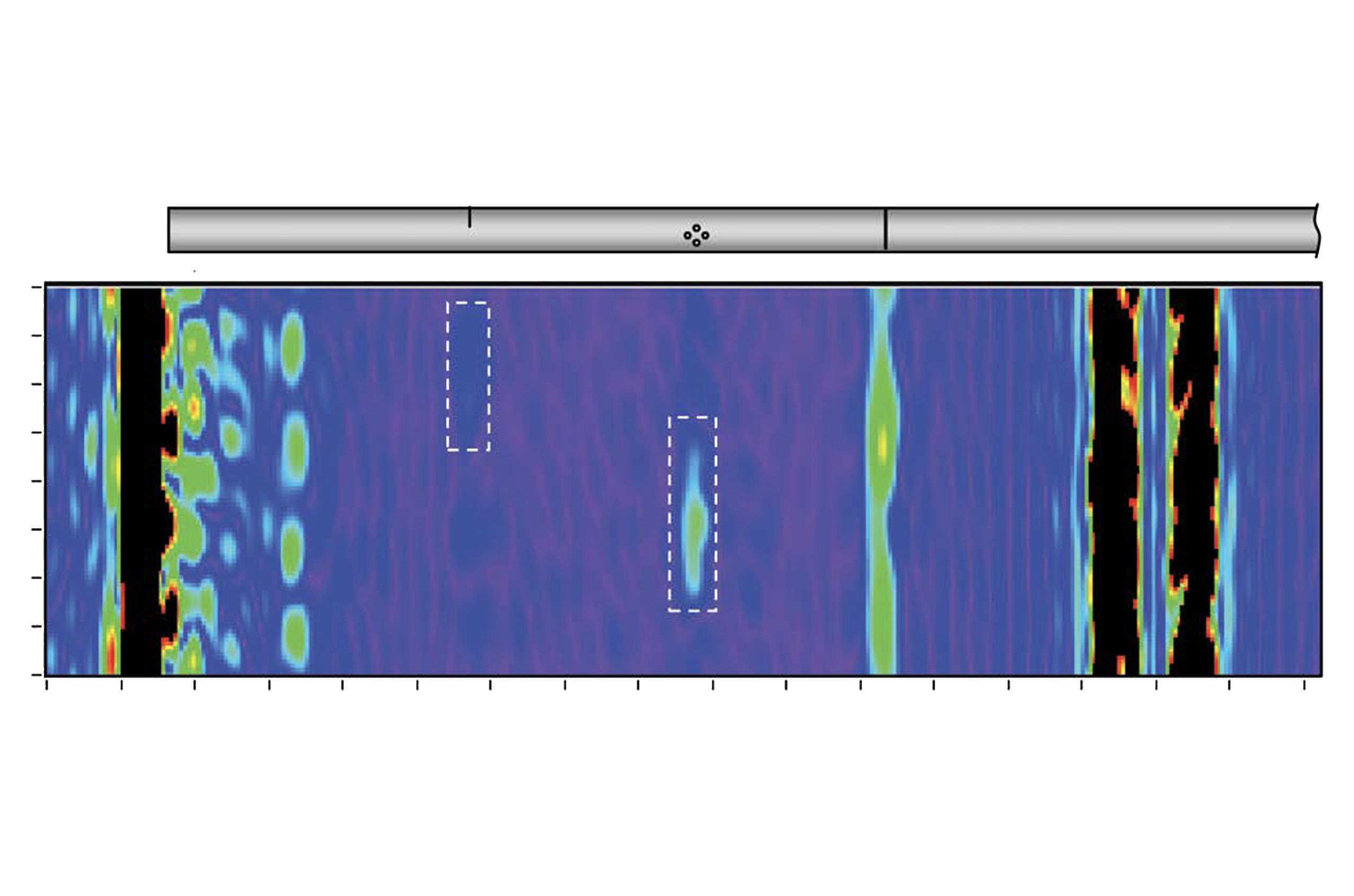
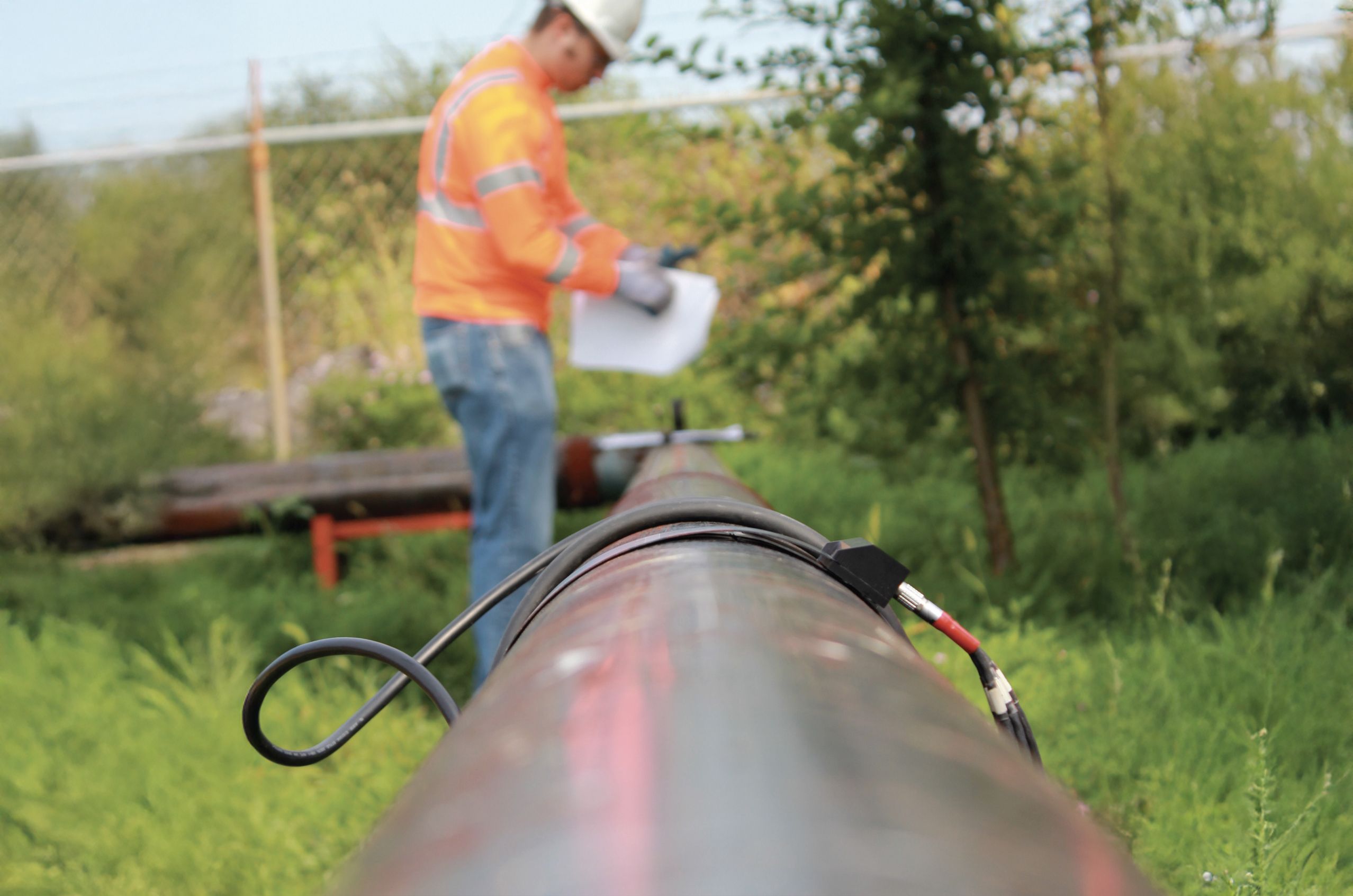
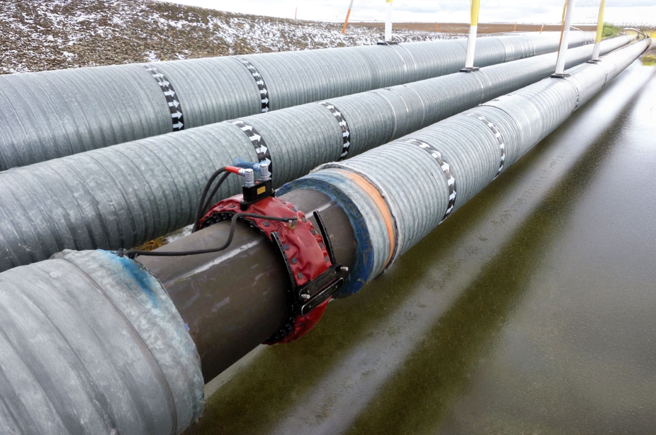
In GW, a ring of sensors is clamped around the outside of a pipe at an accessible location. The sensors generate low-frequency guided wave pulses that travel along the pipe wall in both directions simultaneously. When a pulse encounters a change in the pipe — a weld, a support, thinning from corrosion, or a crack — some of the energy reflects back toward the sensor ring.

(a) A uniform feature like a weld produces a single, predictable reflection back to the sensor ring. (b) An irregular feature like a discontinuity produces additional reflections (shown in red), creating a more complex signal pattern that helps operators distinguish defects from normal pipe features.

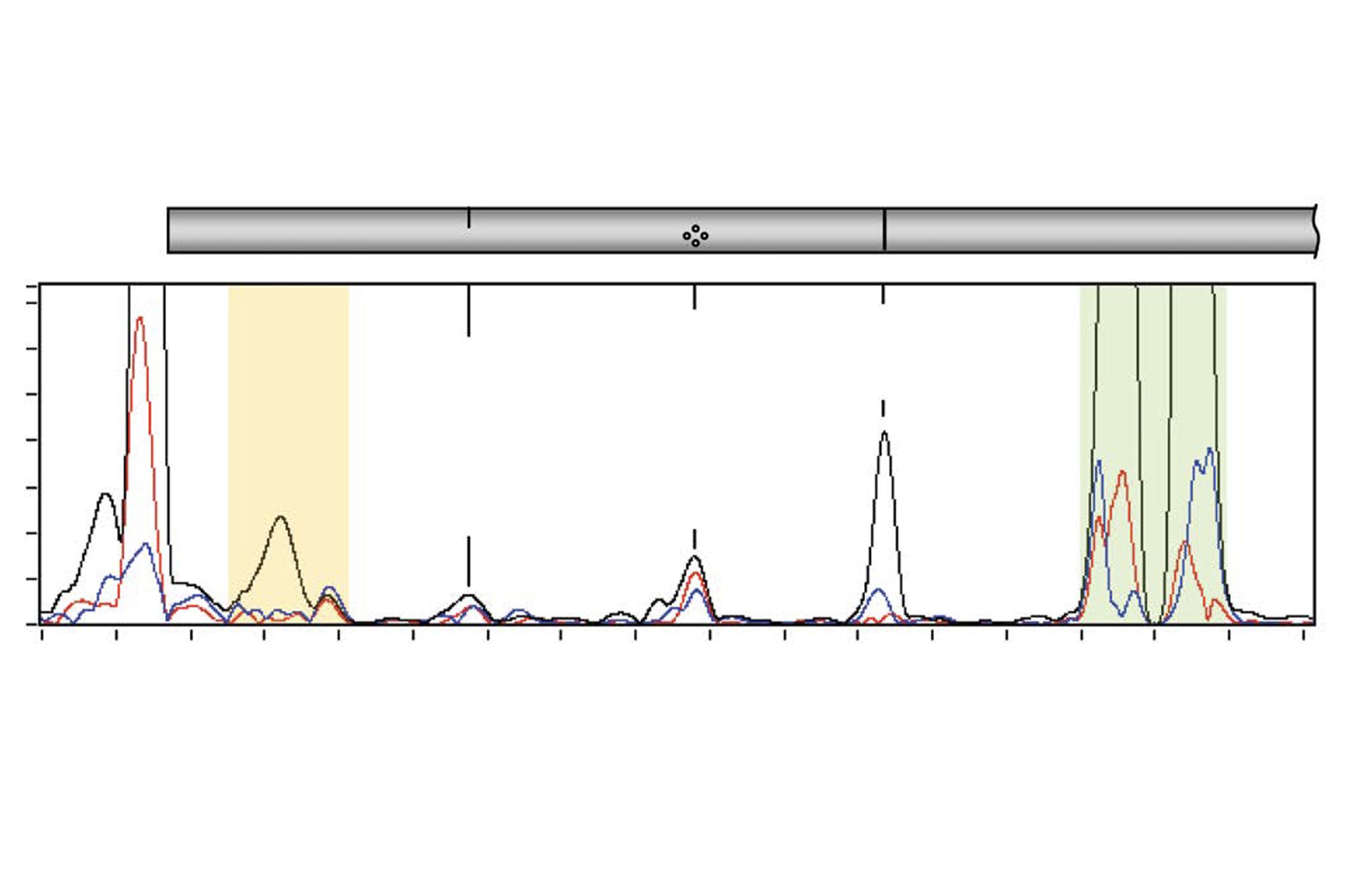
The system records the timing and strength of each reflection. This information tells the operator where features and anomalies are located along the pipe and how significant they may be.

Think of it like shouting into a long hallway. Your voice travels down the hall, and if there is an obstacle or an opening, some of the sound bounces back. GW works on the same principle — but with ultrasonic wave energy traveling inside the pipe wall.

How Guided Waves Travel Through Pipes

Guided waves travel along the wall of a pipe rather than passing straight through the material like a conventional ultrasonic beam. Understanding how these waves behave helps explain both the capabilities and the limitations of GW.

Reflection

When a guided wave hits a change in the pipe wall — such as corrosion that has thinned the metal, a weld, or a support — some of the wave energy bounces back toward the sensor ring. The timing of this reflection tells the operator how far away the feature is.

Attenuation

How quickly the wave loses energy as it travels along the pipe. Coatings, pipe condition, and the material itself all affect how far the wave can travel before it becomes too weak to detect. Understanding attenuation helps operators set realistic inspection ranges.

Mode Conversion

When a guided wave interacts with a feature in the pipe, it can change from one type of wave motion to another. This mode conversion can produce additional signals that need to be identified and interpreted correctly to avoid false calls.

How GW Results Are Read

GW systems display data in formats that help operators identify and locate features along the pipe.

A-scan

Shows signal strength over distance along the pipe. Each peak represents a reflection from a feature like a weld, support, or area of wall loss. Anomalies are categorized by signal strength and reported as an approximate percentage of the pipe's cross-section affected, helping operators prioritize areas for follow-up inspection.

C-scan

Provides a map view showing where around the pipe's circumference a reflection is coming from, helping determine whether wall loss is at the top, bottom, or sides of the pipe.

Worker in an orange vest and helmet inspects a pipeline with cables attached, surrounded by greenery.

How Guided Wave Testing Is Conducted in NDT

GW uses different equipment configurations and inspection approaches depending on the pipe size, material, coating condition, and the goals of the inspection.

Ring Collar Inspection

  • Piezoelectric ring collars are the most common GW setup. A ring of sensor elements is clamped around the pipe and connected to the test instrument. The ring generates and receives guided wave pulses, allowing the operator to screen the pipe in both directions from that single location.

  • Magnetostrictive sensors use a different physical principle to generate guided waves but serve the same purpose and are used in certain applications where piezoelectric rings are less practical.

Long-Range Screening

  • Single-point screening inspects a long section of pipe from one sensor location. The sensor ring stays in place while the system sends waves and records reflections. This is the most common GW inspection approach for in-service pipelines.

  • Permanently installed monitoring leaves sensor rings in place on the pipe for repeated testing over time. This allows operators to track changes in the pipe’s condition from one inspection to the next, which is especially useful for monitoring known problem areas.

In-Line Inspection

  • Guided wave in-line tools can be deployed inside a pipeline to inspect from within, though this is less common than external ring collar methods. These tools are used in specific applications where external access is not possible.

Add Guided Wave Testing Certification to Your Qualifications

ASNT certifications enable you to become a qualified Level II or Level III in GW.

What Certification Is Right for Me?

Industry Applications of Guided Wave Testing

Guided wave testing is used wherever long runs of pipe or tubing need to be inspected efficiently. Its ability to screen large lengths from a single access point makes it particularly valuable where access is difficult or preparation costs are high.

Energy

In oil, gas, and petrochemical facilities, GW is widely used to screen pipelines, process piping, and heat exchanger tubing for corrosion and wall loss. It is especially valuable for inspecting insulated and buried piping that would be costly and time-consuming to access with conventional methods.

"A composite image showcasing various energy sources: solar panels in the foreground, oil pump jacks in the middle ground, and wind turbines and a power plant in the background. The scene illustrates the diversity of energy production methods at sunset.

Aerospace

GW has limited but growing application in aerospace, primarily for inspecting tubular structures and hydraulic lines in aircraft and ground support equipment. Its ability to screen long lengths from a single point makes it useful for inaccessible tubing runs.

A technician performing maintenance or inspection work on the landing gear of a large commercial airplane inside an aircraft hangar. The scene is illuminated with a blue tint, highlighting the aircraft's engines and the structural details of the hangar.

Transportation

In transportation, GW is used to inspect rail tracks, structural tubing in bridges, and piping in ships and offshore platforms. It provides efficient screening of long, continuous structures without requiring full surface access.

A modern high-speed train moving swiftly through a train station at sunset. The motion blur effect emphasizes the train's speed, with vibrant colors in the sky and station lights creating a dynamic and futuristic atmosphere.

Manufacturing

GW is used in manufacturing to inspect long runs of tubing and piping during production and after installation. It supports quality assurance processes by detecting wall loss, corrosion, and welding defects quickly and efficiently.

A modern manufacturing facility with robotic arms working on an automated assembly line. The scene is well-lit with blue overhead lighting, showcasing advanced machinery and precision engineering in a clean, industrial environment.

Infrastructure

GW is particularly useful for inspecting underground piping in water, gas, and wastewater systems, as well as structural tubing in bridges and other civil structures where access to the full pipe length would be costly or disruptive.

A large infrastructure project featuring a highway under construction. Several cranes are positioned along the unfinished sections of the elevated roadway and bridge. The scene is set on a clear, sunny day with blue skies and some scattered clouds.

Example: GW in the Real World

In oil and gas facilities, pipelines often run for long distances and pass through areas that are insulated, elevated, or difficult to reach. Conventional inspection of these lines would require removing insulation, setting up scaffolding, and conducting point-by-point ultrasonic measurements — a slow, expensive process that often has to be repeated across many locations.

GW offers an alternative. A sensor ring is clamped onto the pipe at an accessible point, and guided wave pulses are sent down the pipe in both directions. The reflected signals reveal whether there are any areas of significant wall loss or corrosion along the inspected length — often 30 to 50 meters or more in each direction.

This approach allows operators to screen long sections of piping quickly and focus their detailed inspection resources on the areas where GW has identified a concern, rather than inspecting every meter of every pipe.

Metal pipelines with sensors run parallel, elevated above water, surrounded by a snowy landscape.

Deeper Learning About Guided Wave Testing

ASNT offers both members and nonmembers learning opportunities and resources for NDT specialists certified in GW.

Webpage

Electromagnetic Testing (ET) Courses

Advance your skills and knowledge with courses and webinars on electromagnetic testing.

Book

Programmed Instruction Series: Introduction to NDT

Master the fundamentals of all 16 NDT methods with this comprehensive guide for Level I and II candidates. Covers theory, principles, applications, equipment, and interpretation—plus quiz questions with detailed answer explanations.

Book

Nondestructive Testing Handbook, Vol. 5: Electromagnetic Testing (ET), 3rd ed.

Comprehensive electromagnetic testing reference with an emphasis on modern, digital approaches. Covers core theory, instrumentation, and practical applications across major industries, supporting inspectors, engineers, trainers, and others who evaluate or specify ET work.

Chat Window Trigger